5 Hybrid data model, object-oriented data models
5.1 Hybrid model
This data model arose from the need for joint uniform processing of vector and raster data. Of course, this goal can be achieved by mutual conversion of data between the two basic models (eg conversion of vector data to raster data and their processing together with the original raster data), but such a solution brings a number of difficulties (especially conversion of raster data - vector data) and disadvantages. That is why it is an effort researchers and developers to find a general data model, which would lie somewhere between the two basic models and which would be suitable for storage and data in both vector and raster form. The data would be stored in a very compact form, allowing efficient data processing.
Deren and Jianya (1992) proposed a unified data model that combines the advantages of a vector and raster model to enable simultaneous storage and processing of GIS, DMT and remote sensing data. This model is based on a linear quadtree, ie the geometric description of geo-objects is expressed using Morton keys instead of \(x\) and \(y\) coordinates. To increase the accuracy of the point position representation, the quadtree base cell is further divided by a fine grid (again represented by a quadtree) - the point location is then represented by two Morton keys - the first indicates the point position in the base quadtree and the second in the finely divided grid. The lines are represented here by a set of Morton keys, which contains not only the positions of the start and end nodes and all vertices, but all the way through the basic quadtree. Areas are coded similarly - boundary lines + boundary quadtree cells in this area.
5.2 Object-oriented data models
Geographic information systems have seen a surge in recent years increasing in popularity. A major research and development effort has been made to to improve the functional efficiency of these systems. As a result, some significant improvements, but also the discovery of a number of weaknesses.
The amount of available data has increased considerably (e.g. due to the increasing resolution of of satellite data), leading to storage and processing problems of these data. In analyses, the focus of processing is gradually shifting from spatial to object-oriented analyses. This leads to the need for to introduce object-oriented data representation. This requirement opens up a whole new area of development in GIS technology. With such massive volumes of data, the associated with the problem of how to perform analysis in any system and report the resulting reports. There is a danger that the user will be overwhelmed by too many information. Moreover, it is difficult to know what weight to give to which result, because these results are not put into context.
Today’s data structures are optimized for storage and speed of data manipulation without taking into account the accurate representation of the real world.Geo-elements are reduced to points, lines and areas, or pixels. Data structures primarily focus on the localisation of geo-fragments, thematic data and thus make spatial analyses much more difficult. Neither vector nor raster models exist in the real world - a road is not line, cities are not points, and pixels represent completely arbitrary locations in space, with no defined relationship to a specific geo-frame.
These shortcomings can be eliminated in the only possible way - by creating and implementation of an object-oriented GIS. The necessity of introducing an object-oriented approach to spatial data processing can be demonstrated with a simple example: If we project an image of a landscape to an observer and ask what he sees, he will certainly not tell us that he sees points, lines, or even pixels, but rather forests, roads, valleys, rivers, etc. And this is also the starting platform for the development of object-oriented GIS (OOGIS).
OOGIS must work with objects that correspond to specific real geo features and describe them spatially, thematically and temporally, thematic, relational and functional. This results in multidimensional entities, allowing to deal with problems that were unsolvable using previous data structures. This is for example, overlapping geo-frames, or geo-frames with unclear spatial boundaries (with “fuzzy” constraints). Examples of overlapping geofences can be river and valley. While in classical data models a river always divides a valley into two parts, in OOGIS this situation is not a problem because, although these objects overlap in the 2D space used for the representation, in other dimensions they are completely different. An example of a geoframe with a “fuzzy” constraint can be the valley itself and its adjacent ridge. Again, these two geofeatures may overlap because the line separating them is not precisely and unambiguously defined.
OODBMS (object oriented database management system) provides a much more natural approach to building systems, because program objects correspond directly to real objects. Objects can capture any order of complexity, and using an object-oriented approach, it is therefore easy to store different data types and their complex relationships.
Most of today’s GIS systems use relational databases to store data. However, the use of relational approach is quite new in many areas (it is reported that only 5% of of all data today is stored in relational databases). In this case a question arises whether it would be better to skip the use of relational databases and switch directly to object-oriented databases.
OODBMS offer the best features of modern technologies. Because the objects can contain objects in turn, virtually anything can be affected in an OODBMS complex data structure. These databases offer a natural way to store and to retrieve complex objects, users can define their own objects, allowing them to represent all necessary types of objects in GIS databases geo features (roads, streets, rivers …).
The areas suitable for the use of OODBMS are many and varied. At the public administration level, applications can range from pollution monitoring to construction planning. In the commercial field, these databases can be used, for example, in real estate agencies, where it is very easy to store an accompanying text description, photograph or even video footage of a given property.
The description of geo features represented in GIS databases is relatively complex, consisting of components represented by data, components represented by logical links and last but not least components represented by program code.
The raster data model does not allow full implementation of the description of geo-fragments, moreover, there is a strict separation between the components implemented through data and the components implemented through program code working on these data.
The vector data model allows for an almost complete realisation of the description of geo-fragments, but this description is fragmented into relatively separate parts such as the spatial database, the thematic database and the program code. Moreover, the internal organization of these relatively separate parts often makes the full implementation of the geofragment description difficult.
The Object-oriented data model allows full realization of the description of geoelements, it is characterized by high consistency of the description of geoelements, the individual components of the description of each geo-elements form an organic whole - an object. The disadvantage of the object-oriented data model is its novelty, which may result in some immaturity and, in any case, a limited offer of suitable software products that allow working with this data model and full implementation of all components of the description of geo-fragments.
5.2.1 Object-oriented modelling
OOP (Object-oriented programming) is a software development methodology based on the following ideas:
- Objects - individual elements of the modelled reality (both data and related functionality) are grouped in the program into entities called objects. Objects remember their state and externally provide operations (accessible as methods for calls).
- Abstraction - the programmer, and hence the program they create, can abstract from some of the details of the operation of individual objects. Each object operates as a black box that can perform specified actions and interact with the environment without without requiring knowledge of the way in which it works internally. Encapsulation - ensures that the object cannot directly access the “internals” of other objects, which could lead to inconsistencies. Each object externally accesses the interface by which (and in no other way) the object is worked with.
- Composition - An object may contain other objects.
- Delegation - An object can use the services of other objects by requesting them to performing an operation.
- Inheritance - objects are organized in a tree way, where objects of a type can inherit from another type of object, thereby taking over their abilities to which they only add their own extensions. This idea is is usually implemented by dividing objects into classes, with each object being an instance of a class. Each class can then inherit from another class (in some programming languages, even from several other classes).
- Polymorphism - the referenced object behaves according to which class it is an instance of.
If several objects provide the same interface, they are handled in the same way, but their specific behavior varies by implementation. For polymorphism conditioned on inheritance, this means that where an instance of a class is expected, we can also insert an instance of any subclass of that class, since the class interface is a subset of the subclass interface. For a polymorphism unconditioned by inheritance, it is sufficient if the interfaces (or their required parts) of different classes are the same, then they are polymorphic with each other.
Object
- represents a real entity,
- contains information that describes its properties and behaviour,
- an individual object is distinguished by elements of information that differentiate it from other objects.
The State of an object = the state (form) of the object, i.e. the values of its properties at a given point in time. The change in the state of an object over time is accomplished through an internal action of the object or through the interaction of the object with the environment.
OOP is sometimes referred to as the programming paradigm because it describes not only the way a program is developed and written, but also the way the program designer thinks about the problem.
5.2.2 Unified Modelling Language (UML)
The UML (Unified Modeling Language) iis a graphical language for specifying, constructing, and documenting systems. UML supports the construction of a variety of kinds of diagrams for modeling both structure and behavior of systems. Conceptual modeling of information makes use primarily of structural diagrams, especially package diagrams and class diagrams, which use elements that come from the Kernel package at the core of the UML specification. A simplified description of the principal elements used in package and class diagrams is presented below.
UML supports an object-oriented approach to the analysis, design, and description of software systems. The UML does not specify how it is to be used, nor does it contain a methodology(s) for analyzing, specifying, or designing program systems.
The UML standard is defined by the standards group Object Management Group (OMG).
5.2.2.1 Ways of using UML
- Concept drawing - in this use, the UML is a support tool for communication between developers and for recording ideas and designs. Only things essential to the graphical expression of the design are drawn in diagrams, parts of the design before programming begins. What is important is clarity, speed of drawing and ease of changing or suggesting alternative solutions.
- Detailed Design Drawing - the goal is to record the complete design or complete implementation. In drawing the design, the analyst should cover all elements so that the programmer is able to create the program without much thought about the subject area (there should be no need for the programmer to consult with the user). When drawing detailed designs, specialized programs (CASE) are usually used that are capable of sharing information between models and checking the consistency of the design. In program documentation, tools are often used to generate diagrams from the application’s own code.
- UML as a programming language - in this use, the developer draws UML diagrams from which executable code is generated directly. This requires specialized tools and very precise expression in UML diagrams. In this context, the term Model Driven Architecture (MDA) is very often used, which is another OMG standard that attempts to standardize the use of UML as a programming language.
- Metamodel - this view is used by UML authors and CASE tool authors - they do not look at UML as diagrams, for them the UML metamodel is the basis (diagrams are just a graphical representation of the metamodel). In this approach, the term model is often used instead of diagram, e.g., the term class model is used instead of class diagram. A metamodel is described using Meta-Object-Facility (MOF), an abstract language for specifying, creating and managing metamodels (another OMG standard). The XMI - an XML-based standard (part of the UML standard) is used for metamodel exchange.
5.2.2.2 Conceptual modelling
Conceptual modelling of information uses mainly structural diagrams, especially package diagrams and class diagrams, which use elements originating from the core (core package) of the UML.
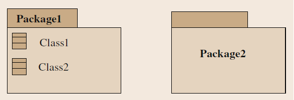
Package identifies the space for a group of elements contained in a package. In the UML diagram it is shown as a rectangle with a smaller rectangle in the upper left corner (Figure 1). The elements contained in the package are shown inside the rectangle, the name of the package placed on the tab. If the elements contained in the package are not specifically displayed, the package name is placed in the larger rectangle.
5.2.2.2.1 Classifier
The fundamental element of a UML class diagram is the classifier. A classifier represents a concept within the system being modeled. It describes a set of objects that have common characteristics. Each such object is an instance of the class.
A classifier is represented by a solid rectangle containing the name of the classifier and, with the exception of the subtype class, a «keyword» that identifies its subtype. The rectangle may be divided by horizontal lines into compartments that contain features of the classifier. There are several types of classifiers.
- Class
A UML class is a type of classifier that has attributes and operations. A class represents a set of objects that share the same set of semantics, properties, and constraints specifications. A class can represent any set of objects, physically existing or not. In GIS, classes are used to represent commonly used feature types, but they can also represent feature properties.
A class is understood as an object, i.e. as a set of attribute values and operations that describe specific instances of the class. A class can represent lamps or entire cities (feature types). It can also represent land ownership or threats to certain species (characteristic features).
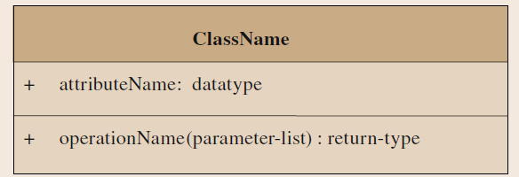
Figure 2: UML class (source: Kresse, Danko, 2012)
The rectangle representing the class (Figure 2) is divided into three “compartments”. The top compartment contains the name of the class and other general properties of the class; the middle compartment contains a list of attributes; the bottom compartment contains a list of operations. Attribute and operation spaces may be suppressed to simplify the diagram. However, suppression does not mean that there are no attributes or operations.
- Interface
An interface describes the service offered by instances of any class that implements that interface. An interface is not an instance in itself, nor does it specify how it is to be implemented in the class that implements it. Rather, it describes the public behavior of the class that implements it. An interface may be implemented by multiple classes, and a class may implement more than one interface.
An example is an interface called Visibility. An Area of Visibility is defined as a two-dimensional polygon that bounds the area on the Earth’s surface from which a given object is visible. The interface can be implemented by any class that represents a physical object. It could be implemented either as an operation that derives the shape from the geometric characteristics of the object and the surrounding terrain, or as an attribute that contains the shape.

Figure 3: UML class (source: Kresse, Danko, 2012)
The interface can be represented as a classifier diagram with the keyword “interface”" at the top of the diagram. The interface diagram can be attached to the diagram representing the class implementation by an implementation symbol, which is represented by a dashed line with an open triangle at the end attached to the interface diagram (Figure 3). The dependency of an implemented class on the interface it implements can also be represented by attaching a circle containing the interface name to the implementing class with a solid line.
- Datatype
A data type is a type of classifier that differs from a class only in that the elements of a data type are identified only by their values. An instance of a datatype cannot exist independently of the property whose value it provides. Data types include primitive predefined types and user-defined types. A data type is identified by the keyword “DataType” at the top of the diagram. Primitive data types include values such as integers and real numbers. An example of a user-defined data type might be a combination of alphanumeric characters used to identify route numbers within the state highway system.
 * **Enumeration** - a type of data type whose instances form a list of named categories. Both the enumeration name and its specific values are declared. An enumeration is a short list of well-understood potential values within a class. An example might be a list of four compass points: east, west, north, and south.
 * **Codelist** - a flexible enumeration specified in ISO/TS 19103 [1.2]. Codelists are useful for long lists of potential values. An enumeration should be used if the elements of the list are completely known; a codelist should be used if only the set of probable values of the elements is known. A codelist can be extended to an application schema. The BuildingUse and LandUse codelists in Figure 4 are examples of codelists. A codelist can be specified by a standard, for example the ISO 639-2 codelist for language identification.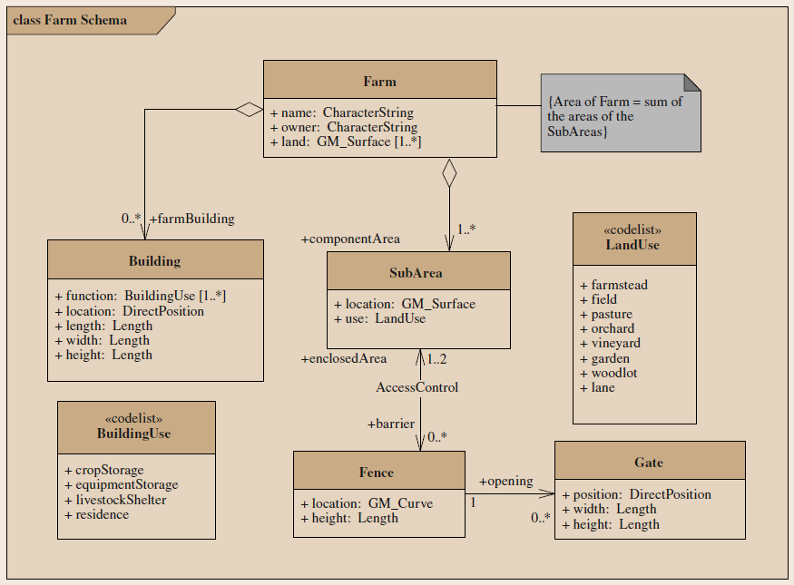
5.2.2.2.2 Feature Class
- Attribute
An attribute represents a characteristic (property) common to objects of a class. Examples of attributes can be the floor plan and height of a building. An attribute is described by a string composed of elements that specify its properties
visibility name: prop-type[multiplicity]=default,
where:
- visibility can be public (+) or private (-). A private element is accessible (visible) only from elements in the space that owns it; public elements are visible to all elements that can access the space that owns it.
- name is a character string that identifies the attribute. The slash (/) before the name indicates that the value of the attribute is derivable from the values of other elements in the model.
- prop-type - the data type of the attribute;
- multiplicity specifies the number of values a class element can have for the attribute. If not displayed, its value defaults to 1.
- default - optional - specifies the initial value of the attribute.
Operation
Operations represent actions that can be performed on the object. Examples are the read and write functions, the aforementioned values of the floor plan and building height attributes. An operation is described by a string consisting of elements that specify its properties.
visibility name(parameter-list): return-type{oper-property},
where:
- visibility can be public (+) or private (-),
- name is a character string that identifies the operation,
- parameter-list is a list of parameters, each in the form
direction parameter-name: type-expression,
where direction can be in, out or inout and defaults to in if the field is omitted, parameter-name is the parameter name and type-expression identifies the parameter data type.
- return-type - data type of the value returned by the operation,
- {property-string} - optional field containing a list of property values applied during the operation.
Association
An association (Figure 5) specifies the connections (relationships) between elements and classes. An association is drawn as a solid line connecting the rectangles of a class. An association can have a name, represented as a string of characters close to the line, but not close to one end. Each end of an association carries information related to the class at that end, including its role name, multiplicity (multiplicity), and navigability. An association between two elements of the same class is expressed as a line that has both ends connected to a rectangle of the same class.

Figure 5: Examples of UML associations (source: Kresse, Danko, 2012)
- Role Name - specifies the behavior of the class at this end with respect to the class at the other end of the association. It is represented by a string starting with a lowercase letter. In Figure 5, the role name “owner” indicates that an instance of class Person is the owner of an instance of class House, while the role name “property” indicates that an instance of class House is the property of an instance of class Person. In data processing, the role name is used to identify the subset of class instances that are involved in the association. For example, it can be used to select owners from a set of Person instances contained in a database.
Multiplicity
Multiplicity specifies the number of elements of a class that can be associated with the class on the other side of the association. We read the multiplicity of the aforementioned relation between persons and properties as follows: A group of persons can have any number of members (we know this by the asterisk next to the class Person). A person can own 1 to any number of houses (we know this by the 1..* for the House class).
Let us now list the different possible notations of multiplicity:
- 1 (number) - indicates a specific value (here just 1)
- (asterisk) - denotes an arbitrary number (hence 0). Instead of the asterisk, we can find the symbol N in some materials.
- 1..* (interval) - with 2 dots we can mark the interval.
We insert the symbols we already know, e.g. 2..6 or 1..* or 0..1.
We can even merge entries, e.g. like this: 1, 2, 3, 7..*. This notation indicates multiplicity of 1, 2, 3 or 7 or more. If no multiplicity is specified, this indicates a default value of 1.
Figure 5 shows the following examples of associations:
- An instance of the House class can be owned by one or many owners.
- A person can be the owner of none or many houses.
- A class Play consists of at least one and potentially many instances of a class Act.
- An instance of class Act belongs to only one instance of class Play.
- An element of class Triangle associates just three points as vertices.
- An element of class Points serves as a vertex to any or many triangles.
We use the same multiplicity expression for attributes.
Navigability
Navigability describes the ability of one element to use information contained in another element. An arrow attached to the end of a path association indicates that navigation is enabled in the system in the direction of the class attached to the arrow. In other words, the information contained in that class is accessible from the class at the other end of the association. For example,
Figure 5 shows that it is possible to navigate from an instance of the Triangle class to obtain information about the elements of the Point class that make up its vertices, but it is not possible to navigate from an instance of Point to identify the instances of triangles that it serves as a vertex.
Aggregation
Aggregation represents a whole-part relationship. It is drawn as a solid line, terminated on one side by an empty diamond. This is placed next to the entity that represents the whole (e.g. triangles). Thus, from an implementation point of view, it is the entity that holds the collection of elements. The entity representing the part can exist by itself and be part of other collections as well.
For example, the element of class Triangle in Figure 5 is the collection (aggregation) of three elements of class Point. Aggregation is considered a weaker form of composition.
>
Composition
Composition is similar to aggregation, but represents a stronger relationship. The entity of the part is meaningless without the whole. If the whole ceases to exist, the parts automatically cease to exist. We draw a composition the same way as an aggregation, but the rhombus is full. For an entity representing the whole, the multiplicity must always be 1. This binding tends to be confusing and I would recommend avoiding it and replacing it with aggregation.
For example, the class Play in Figure 5 is made up of one or more elements of the class Act.
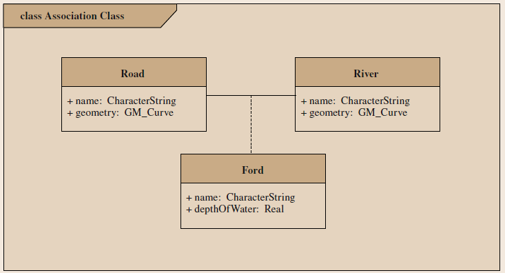
Association class
An association class is a class that mediates the relationship between two entities. The advantage is that it can supply some attributes to the relationship. An example often given is the Person and Departure classes, where the Ucast associative class assigns a person to a tour and supplies the arrival and departure times. Another example is Person and Hotel, where the hotel has no fixed check-in time and is booked by a specific person. A similar class could still be between an employee and a company, for example, where it would define the employee’s salary. Another use could be the possibility to create an M:N binding in this way, similar to how it works for databases. The association class would thus hold a collection of references. In Figure 6, the Ford class is modeled as an association between the Road and River classes.
Generalization
Generalization is a taxonomic relationship between more general and more specific elements. The more specific element is fully consistent with the more general element and contains additional information. An instance of the more specific element may be used where the more general element is allowed. The generalization is shown as a solid line connecting the more specific element (e.g., subclass) to the more general element (e.g., superclass) by a large empty triangle where the line meets the more general element. An abstract class, which has its name expressed in italics, can be created as an instance of its subclasses. Sometimes a superclass is defined as an abstract class if it has no attributes, but rather is created in order to establish a clear hierarchy of the model. The resulting dataset has no objects that are named after the abstract class. Figure 7 shows an example of two generalization relationships in which each of the two subclasses of the Vehicle class has a third attribute in addition to the two attributes inherited from the Vehicle (*Vehicle) class.
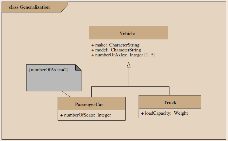
Figure 7: Example of generalization (source: Kresse, Danko, 2012)
The individual generalization relations can be grouped into generalization sets, each of which represents one possible way of partitioning the superclass. For example, the superclass Person can be split into one generalization determined by gender and another generalization determined by education level.
Each set of generalizations has a name that is appended to the lines connecting the subclasses to the superclass.
Stereotype
Stereotypes extend the semantics of existing elements but do not affect their structure. A stereotype is identified by a name as follows:<
Note
The note contains textual information. It is shown as a rectangle with a curved upper right corner, attached to any one or more elements of the model by a dashed line. Notes
can be used to store comments or constraints. The example in Figure 7 contains a constraint.
Constraint
A constraint specifies a semantic state or restriction. Although the UML specification includes Object Constraint Language for writing constraints, constraints can be written using any formal notation or natural language. A constraint is displayed as a text string in parentheses “{}”. It is contained in a note or placed near the element to which it relates. Figure 7 shows an example of a constraint on the value of the numberOfAxles attribute that PassengerCar inherits from a vehicle.
If the element notation is a text string (e.g. attribute), the compound parentheses containing the constraints can be followed by the element text string. Constraints included as element in a list applies to all subsequent elements in that list until the next constraint or the end of the list appears.
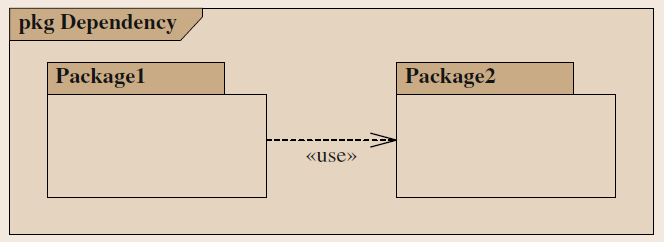
Dependency
Dependency indicates that the implementation or operation of one or more elements requires the existence of one or more other elements. Thus, it creates relationships between the elements of the model with each other. It is shown as a dashed arrow between model elements. The element at the end of the arrow (client) depends on the element at the beginning of the arrow (provider). The type of dependency can be indicated as a keyword as follows: <
5.2.3 The General Feature Model (GFM)
ISO/TC 211 introduced the GFM described in ISO 19109 as a metamodel for representing elements in an application schema. Elements of the metamodel can be represented as elements of a UML model of the application schema. Those that cannot be expressed graphically should be included in the model documentation, which may be in the form of a data dictionary of the application schema.
5.2.3.1 GF_FeatureType
The main element of the GFM is the GF_FeatureType metaclass (Figure 9). Example A GF_FeatureType is a UML class named for a specific type of feature, such as a bridge, factory, or road. A GF_FeatureType has three attributes that are assumed to be included in each feature:
- typeName - contains the name of the specific feature type represented by the created class,
- definition - contains the definition of the feature type and is “carried” as an attribute of the class,
- isAbstract - contains a boolean value indicating whether or not the created class is abstract. If the value is TRUE, the UML class name is displayed in italics to indicate an abstract class.
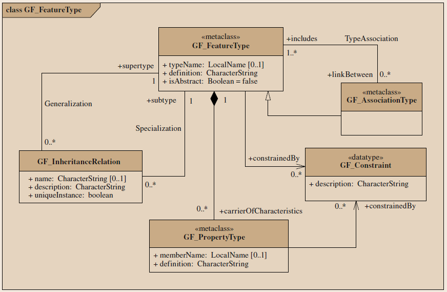
5.2.3.2 GF_InheritanceRelation
The GF_FeatureType metaclass is linked to the GF_InheritanceRelation class by two associations of generalization and specialization. This structure shows that two elements of the GF_FeatureType class can be related to each other as a superclass and subclass in a generalization hierarchy.
Since the name (name) of the GF_GeneralizationRelation attribute is optional, the description and uniqueInstance attributes are required. The uniqueInstance attribute contains binary values: TRUE … a superclass element can be an element of only one subclass, FALSE … a superclass element can be an element of more than one subclass.
The GF_InheritanceRelation element is modeled as a UML generalization relation. The optional attribute name can be attached to a generalization relation if it is part of a generalization set, in which case each member of the set must have the same name. Otherwise, this attribute should not be implemented. The description of the description attribute is contained in model documentation. The default setting {overlapping} constraint of the generalization set is expressed by setting the uniqueInstance attribute to true. There should be used overlapping constraint. of the generalization set if the value of uniqueInstance is false.
Let consider the example in Figure 10. The element type Building (Building) has two subclasses: school (School) and hospital (Hospital). The Building element type has three attributes: length, width* and numberOfStories, which are inherited by both of its subclasses. Each subclass has specific attributes: for schools: educational level (educationalLevel) and numberOfTeachers; for hospital: number of beds (numberOfBeds). The two generalization relations belong to a generalization set called Function.
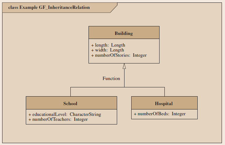
Figure 10: Example of inheritance (source: Kresse, Danko, 2012)
All three classes (buildings, hospitals, schools) are elements of the GF_FeaturType GFM metaclass. The hierarchical relationship in which buildings are a generalization of hospitals and schools is the result of applying GF_InheritanceRelation to the class.
5.2.3.3 GF_AssociationType (asociační typ)
Existují dva vztahy mezi GF_FeatureType a GF_AssociationType:
- Asociace nazvaná TypeAssociation na obrázku 9 indikuje, že může být prvek třídy GF_FeatureType součástí prvku GF_AssocitationType. Obecně, GF_AssociationType je implementován v aplikačním schématu jako jednoduchá UML asociace mezi dvěma třídami, které reprezentují různé typy prvků.
- Druhý vztah mezi GF_FeatureType a GF_AssociationType je vztah dědičnosti, který z GF_AssociationType vytváří podtřídu GF_FeatureType.
Jako podtřída GF_FeatureType zdědí GF_AssociationType tři atributy GF_FeatureType, i když je v případě GF_AssociationType název nepovinný. GF_AssociationType také zdědí asociace GF_FeatureType. To znamená, že může obsahovat vlastnosti, v tomto případě může být modelována v aplikačním schématu raději jako asociační třída UML než jako asociace UML. Dalším typickým příkladem je most, který lze modelovat jako silniční úsek nebo jako samostatný prvek se zvláštní
informací o nadjezdu. V prvním případě může být most jednoduše asociován se dvěma dalšími silniční segmenty. V dalším je most instancí GF_FeatureType.
5.2.3.4 GF_Constraint (omezení)
GF_FeatureType i GF_PropertyType jsou asociovány s GF_Constraint. GF_AssociationType dědí tuto asociaci z GF_FeatureType. GF_Constraint představuje popis omezení, které může být aplikováno na případ jakékoliv asociované metatřídy. Příkladem je silnice, která na které je povolen pohyb pouze dopravním prostředkům s rychlostí vyšší než 60 km/h.
5.2.3.5 GF_PropertyType (typ vlastnosti)
Jak ukazuje asociační vztah mezi GF_FeatureType a GF_PropertyType (obrázek 9), třída typ prvku může obsahovat nulu pro mnoho instancí z GF_PropertyType. GF_PropertyType je abstraktní metatřída se třemi podtřídami: GF_AssociationRole, GF_AttributeType a GF_Operation, z nichž každá reprezentuje jiný typ vlastnosti, který může být přiřazen ke třídě typu prvku. Třída GF_PropertyType obsahuje pouze název a popis typu vlastnosti (atributy memberName a description). Všechny další podrobnosti jsou obsaženy v podtřídách.
GF_PropertyType (obrázek 11) má dva atributy, které jsou zahrnuty v každém případě:
- memberName obsahuje název typu vlastnosti představovaný instancí;
- definition obsahuje definici tohoto typu vlastnosti.
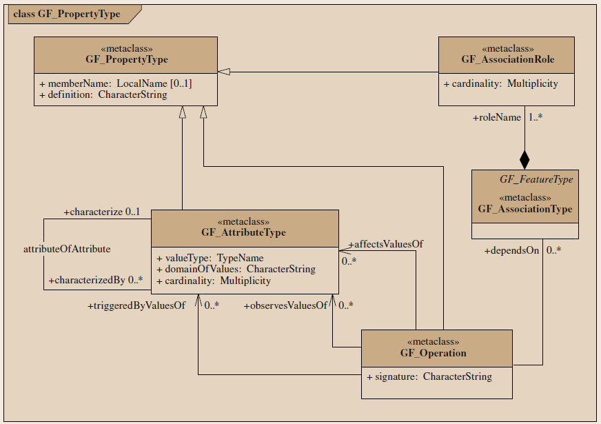
5.2.3.6 GF_AssociationRole
GF_AssociationRole describes the role that an instance of the item type can have in the association with another instance of the same or another type. The GF_AssociationRole inherits the member name (memberName) and definition (definition) attributes of the GF_PropertyType. The additional attribute cardinality (cardinality) specifies the multiplicity for instances of the element type acting in a given role. The GF_AssociationRole inherits the association with GF_Constraint from GF_PropertyType, but also has an association from GF_AssociationType that specifies that it is part of an instance of GF_AssociationType.
In the UML diagram, the memberName and cardinality attributes are expressed by the role of the name and multiplicity at the end of the line representing the association. The definition attribute is included in the model documentation.
Consider the example in Figure 5, where the name role property indicates that an instance of class House may be owned by one or more instances of class Person with role owner.
5.2.3.7 GF_AttributeType
The GF_AttributeType instance describes the type of the attribute that belongs to a specific item type. In addition to the memberName and definition attributes, GF_AttributeType has attributes that it inherits from GF_PropertyType. The valueType attribute specifies the data type of the attribute. The domainOfValues attribute identifies the set of values that the attribute can take on. Attribute cardinality cardinality specifies the multiplicity of the attribute type of the element.
The GF_AttributeType inherits the association with GF_Constraint from GF_PropertyType, but also has an association to itself called attributeOfAttribute. This shows that an attribute can itself have attributes. In this case, the attribute is modeled as a UML class that can be used as a data type for an attribute or associated with an element type.
The UML attribute representation includes memberName, datatype and cardinality. The definition of domainOfValues must be specified in the data dictionary.
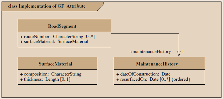
Figure 12 illustrates three ways in which GF_FeatureAttribute can be expressed in an application schema. The routeNumber attribute of the RoadSegment feature is specified within the attribute part of the RoadSegment class. The surfaceMaterial attribute itself has the attributes; it is specified within the attribute space of the class diagram, but uses as its data type a separately defined one. The maintenanceHistory element attribute, which also has attributes, is modeled as a separate class attached to the element by association. Note that the role name at the end of the UML association is analogous to the attribute name for the class at the other end of the association.
5.2.3.8 GF_Operation
The GF_Operation instance describes the associated with the item type. In addition to the memberName and definition attributes that inherit from GF_PropertyType, GF_Operation has an additional signature attribute that provides the name, arguments, and output types.
As an example, consider an operation called trafficFlow, which serves as a property of the Highway element type. Such an operation may have a signature
trafficFlow(dayofWeek:DayName, timeofDay:Time):vehiclesPerHour:Integer.
This signature indicates that the operation accepts the day of the week and time of day as input parameters and returns the number of vehicles per hour as output (integer).
The GF_Operation inherits the association with GF_Constraint from GF_PropertyType, but also has four additional associations. The three with GF_AttributeType describe how an instance of GF_Operation can use one or more attribute values. The triggerdByValuesOf role identifies the attribute types that serve as triggers for the operation. The observesValuesOf role identifies the attribute types that are used as input parameters for the operation. The affectsValuesOf role identifies the type of attribute that is the output parameter of the operation. The association with GF_AssociationType identifies the paths by which an instance of GF_Operation obtains information about the attributes it uses.
5.3 Sample application diagram
This section presents an example of a simple application schema developed according to the principles described in this chapter. The schema conforms to the GFM and is described in UML.
The example is an application schema for describing the spatial characteristics of a single farm. Its content includes those features that can be displayed on a map (Fig. 12). The features are provided with sufficient attribution to distinguish one instance from another. The schema makes use of three of the geometric object classes specified in ISO 19107 to describe the spatial position and geometry of these feature types. The objects selected are those appropriate for the two-dimensional coordinate space of a map.
In this schema, a Farm has three attributes: name, owner, and an area represented as a GM_Surface. The multiplicity of the land attribute indicates that a Farm may consist of noncontiguous land areas. A Farm aggregates instances of two other types of features: SubAreas and Buildings. A Farm must have at least one SubArea but need not have any Buildings. The plain language constraint on Farm indicates that the entire area of the farm must be included in its aggregated instances of SubArea. The navigability designations show that it is possible to query a Farm object in order to determine which instances of SubArea and Building are contained in the Farm, but it is not possible to query a Building or SubArea object to determine what instance of Farm it belongs to.
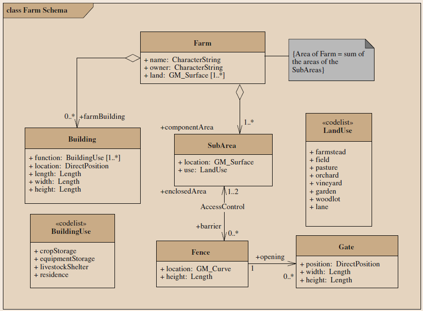
Figure 12: Simple farm diagram (source: Kresse, Danko, 2012)
The SubArea and Building feature types have properties that describe their location, geometry, and use. Note that neither feature type has an identifier attribute; instances can be distinguished from each other by their locations. The spatial relationships between SubAreas and Buildings are not described by associations because they can be derived from their location attributes.
A Building is treated as a point object, so its location is described as a DirectPosition. Its size is described by three required attributes that provide its dimensions using the Length measure specified in ISO/TS 19103 [1.2] as their datatype. Its function is identified by one of the values from the code list BuildingUse; a Building may have more than one function.
A SubArea is treated as a two-dimensional object. Both its location and its geometry are described by the geometric object GM_Surface. Its use is identified by one of the values from the code list LandUse.
The named association AccessControl shows that access to a SubArea may be restricted by a set of Fences. The multiplicity at the enclosedArea end of the association reflects the fact that every instance of Fence separates two areas, but one of these areas may be excluded from the data set because it is outside the boundaries of the Farm. The multiplicity at the other end of the association supports unfenced instances of SubArea but is unlimited because each of the contiguous instances of SubArea is considered to be separated from this instance by a unique instance of Fence. This association is navigable in both directions, meaning that it is possible to determine the characteristics of any instance of Fence that bounds an instance of SubArea, and to determine the characteristics of the instances of SubArea that are bounded by any instance of Fence.
A Fence is treated as a one-dimensional object whose geometry is described by a GM_Curve, but it is also given a height attribute. An instance of Fence may have a set of zero to many openings, each controlled by an instance of Gate. Each instance of Gate is associated with only one instance of Fence. The navigability of the association means that a Fence object knows about the associated instances of Gate but not vice versa.
A Gate is treated as a point object so its location is described as a DirectPosition, but it is also given height and width attributes.